1.Product Overview
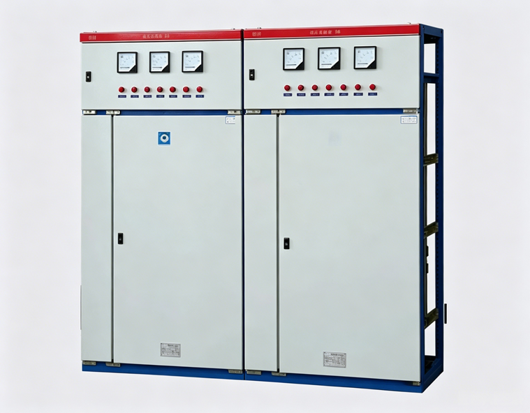
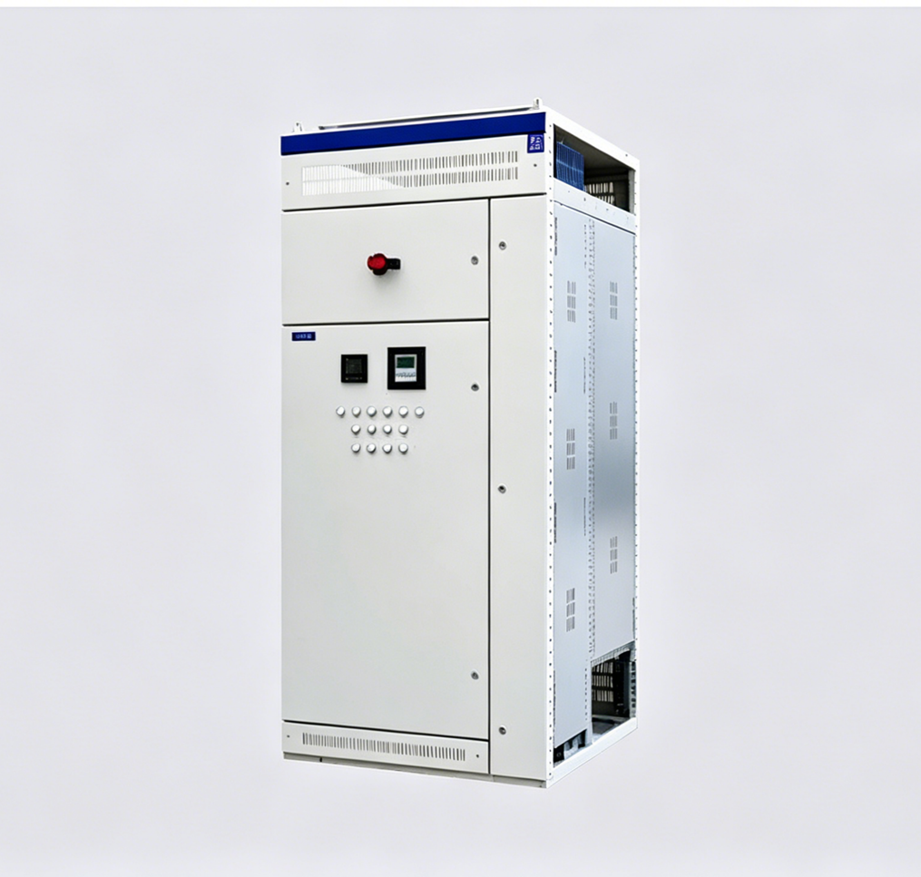
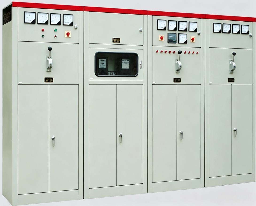
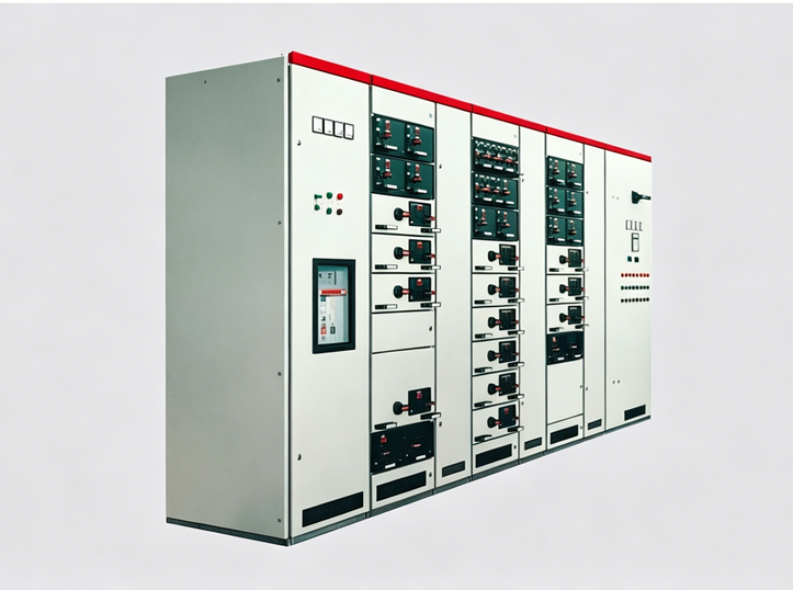
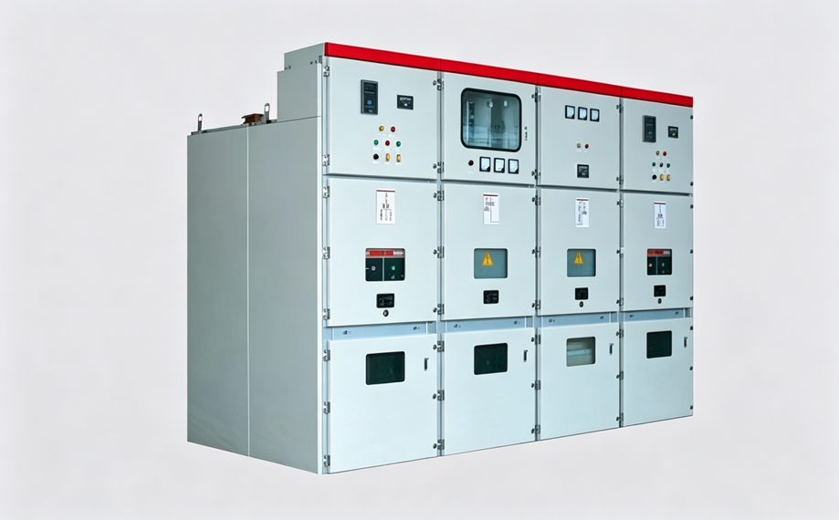
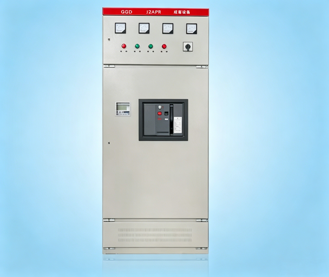
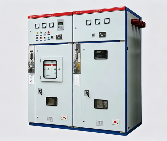
The HXGN□-12 type box‑type (fixed) metal‑enclosed ring main unit (referred to as RMU) is a new type of high‑voltage switchgear produced to meet the needs of urban power grid renovation and construction. It is used in power supply systems for making and breaking load currents as well as making short‑circuit currents. This RMU is equipped with a vacuum load switch, and the operating mechanism is a spring operating mechanism, which can be operated either manually or electrically. The switch and isolating blade are provided with manual operating mechanisms. This RMU features high reliability, compact size, no risk of fire or explosion, and is equipped with reliable "five‑prevention" functions.
2.Operating Environment Conditions
1. Altitude not exceeding 1000m;
2. Ambient temperature range: -5°C to +40°C;
3. Relative humidity: daily average not exceeding 95%, monthly average not exceeding 90%;
4. Locations free from conductive dust, corrosive gases, and water vapor;
5. Locations without risk of fire or explosion, and without frequent violent vibration.
3.Scope of Application
The ring main unit (RMU) is suitable for use in AC 10kV, 50Hz power distribution systems. It is widely used in urban power grid construction and renovation projects, industrial and mining enterprises, high‑rise buildings, public facilities, etc., serving as a ring network power supply unit and terminal equipment, playing a role in power distribution, control, and protection of electrical equipment. It can also be installed in compact substations. This RMU complies with the relevant provisions of IEC 420 "High‑voltage alternating current switch‑fuse combinations" and GB 3906‑91 "Alternating‑current metal‑enclosed switchgear for rated voltages of 3‑35kV."
4.Ring Network Power Supply Principle
Ring network power supply generally consists of three basic units. The incoming and outgoing line cabinets serve as the ring network units. When a fault occurs on any line, it can be isolated in a timely manner, and the other unit ensures continuous power supply to the user's transformer circuit. The ring main unit in the user's circuit provides protection and isolation for the transformer, facilitating maintenance and repair. The RMU can be extended arbitrarily and can form a variety of combination schemes based on the basic units according to user requirements, enabling any combination scheme for any substation or distribution station.
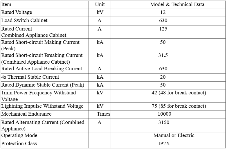
5.Main Technical Parameters
6.Structural Characteristics
1. Structural Performance Characteristics
The enclosure of the ring main unit (RMU) is a closed structure consisting of a basic framework, top plate, front panel, and side panels. The top part of the RMU is the busbar compartment, and in front of the busbar compartment is the instrument compartment, with the two separated by a steel plate. The upper part of the cabinet houses the load switch compartment, while the middle and lower parts accommodate cable incoming/outgoing terminals and other component compartments. The RMU mainly consists of a vacuum load switch, isolating switch (or isolating blade fuse with fuse), earthing switch, surge arrester, operating mechanism, interlocking mechanism, and measuring and metering circuits.
2. Functional Units
The RMU is mainly equipped with the FZN21-12/630 type two‑position vacuum load switch. The primary configurations are the incoming line cabinet and the outgoing line cabinet.
A. Incoming line cabinet configuration
The cabinet is equipped with one FZN21-12/630 type two‑position vacuum load switch. CT and PT can also be flexibly installed inside the cabinet. The main circuit, consisting of one FZN21-12/630 vacuum load switch fitted with an isolating blade, can achieve two positions: busbar connection and isolation.
B. Outgoing line cabinet configuration
The cabinet is equipped with one FZN21-12/T125-31.5 load switch‑fuse combination unit. CT, PT, and ZnO surge arresters can be flexibly installed inside the cabinet. In the fuse‑combination unit, the fuse tube is provided with a striker pin. Under short‑circuit conditions, the striker pin strikes the trip mechanism to achieve rapid interruption, effectively protecting electrical equipment.
C. "Five‑Prevention" interlocking functions
a) Energization operation: Only when the cabinet door is closed and locked, and the earthing switch is operated to the "open" position, can the load switch be operated to the closed position.
b) De‑energization operation: When the load switch is in the open position, the earthing switch can be closed. When the earthing switch is in the closed position, the insulating barrier must be inserted into place before the cabinet door can be opened.
c) The vacuum interrupter and the isolating blade have a reliable interlock. The isolating blade and the earthing blade are interlocked with each other and also interlocked with the cabinet door. The insulating barrier is also interlocked with the cabinet door.
d) Mechanical interlocking can also be achieved between two incoming line cabinets, and between an incoming line cabinet and an isolation cabinet.