1.Product Overview
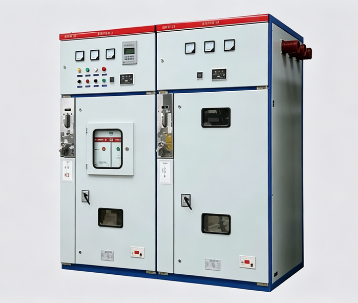
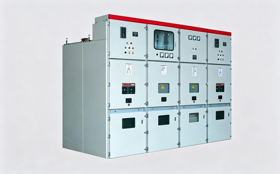
The KYN28A-12 (GZS1) type indoor metal-clad, middle-mounted withdrawable switchgear (hereinafter referred to as the switchgear) is a three-phase AC 50Hz indoor complete set of power distribution equipment, used for receiving and distributing electrical energy in 3–12 kV networks, as well as for controlling, protecting, and monitoring the circuits.
A variety of microprocessor-based integrated relay protection devices can be installed on the relay compartment panel of this product, enabling intelligent system control with functions such as remote control, remote measurement, remote signaling, and remote adjustment. A CAN bus with a communication interface is used to control the field network. The switchgear also features functions to prevent incorrect operations, including: preventing the operation of the circuit breaker under incorrect conditions, preventing the handcart from being pushed or withdrawn under load, preventing the closing of the earthing switch when the circuit is live, preventing the supply of power when the earthing switch is in the closed position, and preventing access to live compartments. These are collectively referred to as the "five-prevention" functions. The switchgear can be fitted with VS1 (i.e., ZN63) or ZN12V vacuum circuit breakers, as well as imported VD4 vacuum circuit breakers or VC series vacuum contactors.
2.Basic Electrical Parameters
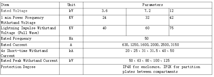
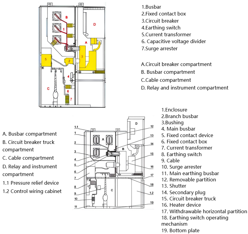
3.Schematic diagram of switchgear structure
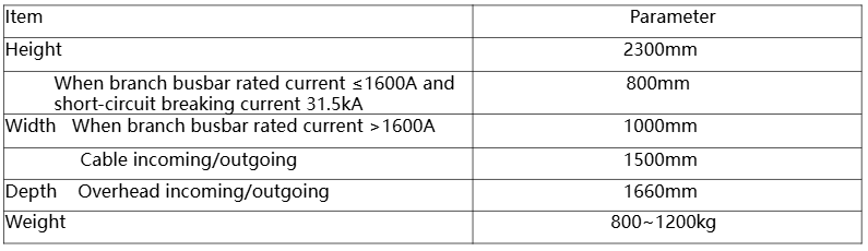
4.Overall Dimensions
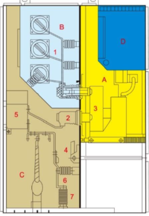
5.Switchgear structure
A.Truck
The truck frame is made of thin steel plates processed by CNC machine tools, then riveted and welded. Depending on the application, the truck can be classified into circuit breaker truck, voltage transformer truck, isolator truck, metering truck, etc. Trucks of the same rating can be easily interchanged. The truck has three positions within the switchgear: the isolated position, test position, and service position. Each position is provided with a positioning device to ensure that the truck cannot be moved arbitrarily when in any of the above positions, and the interlock must be released before moving the truck. The mechanical interlock is safe, reliable, and flexible.
B. Busbar Compartment
The busbar is routed from one switchgear to another and is fixed by means of branch busbars and fixed contact boxes. The flat branch busbars are bolted to the fixed contact boxes and the main busbar, without requiring any additional clamps or insulators for connection. When required by the user or for special engineering needs, the bolts on the busbar can be insulated and sealed with end caps. Where the busbar passes through the partition between switchgear sections, it is secured by busbar bushings. In the event of an internal fault arc, this design limits the spread of the fault to adjacent cabinets and ensures the mechanical strength of the busbar.
C. Cable Compartment
The cable compartment can accommodate current transformers, earthing switches, surge arresters, and cables. A slotted removable aluminum plate is provided at the bottom to facilitate on‑site construction.
D. Relay and Instrument Compartment
The relay and instrument compartment is used for mounting various components such as relays, instruments, indicating lights, and control switches. In addition, a small busbar compartment can be added on top of this compartment upon user request, allowing up to sixteen control busbars to be routed.
Pressure Relief Device
Pressure relief devices are installed above the circuit breaker compartment, busbar compartment, and cable compartment. When an internal fault arc occurs in the circuit breaker, main busbar, or cable compartment, the arc causes the internal air pressure inside the switchgear to rise. Once the pressure reaches a certain level, the pressure relief metal plate on the top device automatically opens, releasing the pressure and expelling gases to ensure the safety of both operating personnel and the switchgear.
Latching Mechanism
The connection between the middle door and the cabinet body adopts a latching mechanism, supplemented by a lifting device, making it easier to open the middle door. When the middle door is in the closed position, the connection strength between the door and the cabinet body is improved, enhancing the ability to effectively withstand internal arcing faults.
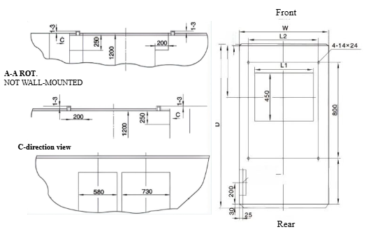
5.Schematic diagram of switchgear installation foundation
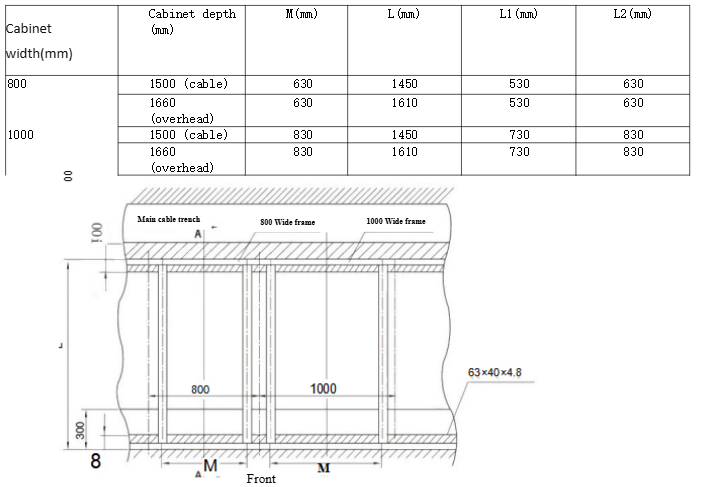
A-A rotation
Switchgear installed away from the wall