1.Product Overview
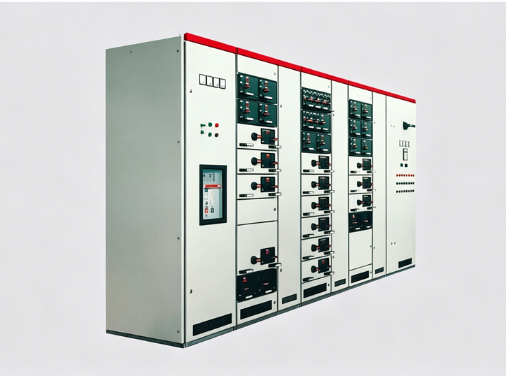
This series of low-voltage withdrawable switchgear is suitable for use in power plants, substations, petrochemical plants, metallurgical rolling mills, transportation and energy facilities, light industry andtextilefactories and mines, as well as residential communities, high-rise buildings, and other locations. It is intended for the conversion, distribution, and control of electrical energy in power systems with a rated working voltage up to AC 660V and a frequency of 50–60 Hz.
This equipment complies with national standards GB7251 "Low-Voltage Switchgear Assemblies" and JB/T 9961 "Low-Voltage Withdrawable Switchgear Assemblies," as well as international standards such as IEC 439-1 and VDE 0660 Part 5.
2.Operating Conditions
1. The ambient air temperature shall not exceed +40°C and shall not be lower than -5°C, and the average temperature over a 24‑hour period shall not exceed +35°C.
2. Atmospheric conditions: The air shall be clean. The relative humidity shall not exceed 50% at a maximum temperature of +40°C. Higher relative humidity is permitted at lower temperatures, e.g., 90% at +20°C, but due to temperature variations, occasional condensation may occur.
3. The altitude shall not exceed 2000 m.
4. The equipment is suitable for transportation and storage within a temperature range of -25°C to +55°C, and for short periods (not exceeding 24 hours) up to +70°C. Under these extreme temperatures, the equipment shall not suffer any irreversible damage and shall be capable of normal operation under standard conditions.
5. If the above operating conditions cannot be met, the matter shall be resolved through negotiation between the user and the manufacturer.
6. When the equipment is to be used on offshore oil drilling platforms or in nuclear power plants, a separate technical agreement shall be concluded.
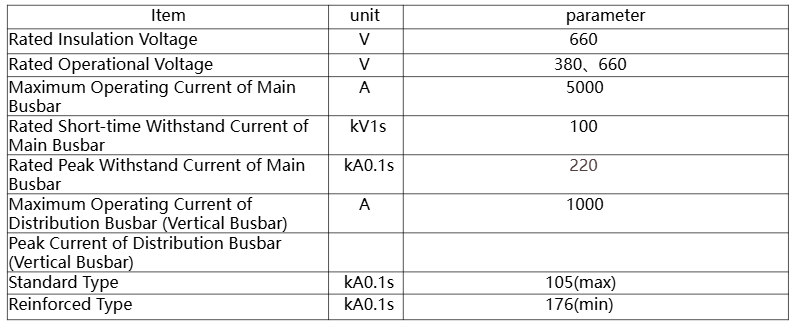
3.Basic Electrical Parameters
4.Switchgear type
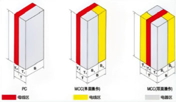
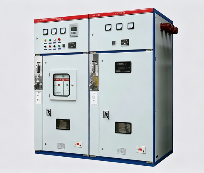
1. Power Distribution Center (PC): Can be equipped with circuit breakers of the Emax, MT, 3WN, AH, ME series, etc.
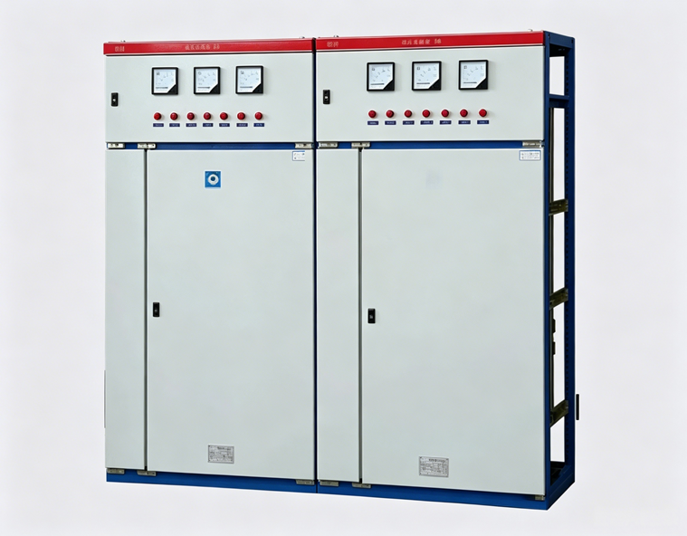
2. Motor Control Center (MCC): Assembled from large and small drawers. The main switch of each circuit adopts a high‑breaking molded case circuit breaker or a rotary load switch with fuses.
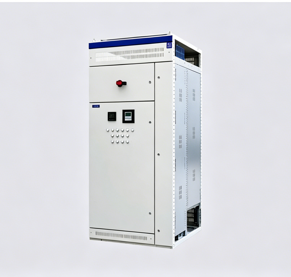
3. Automatic Power Factor Correction Cabinet (with manual, automatic, and remote power factor compensation devices).
A.Power Distribution Center (PC) cabinet

B.Motor Control Center (MCC) cabinet

5.Cabinet schematic diagram